3. Chapter 3: Pre-processor Programs
3.1. Introduction
There are two pre-processor programs to help to create or edit the FLO-2D data files: QGIS Plugin, and PROFILES. Tutorials and workshop lessons for some of the programs’ functions are available in the FLO-2D/flo_help subdirectory. A discussion of the commands in the PROFILES program is included in this manual.
3.2. QGIS FLO-2D Plugin
The FLO-2D Plugin for Quantum Geographical Interface System (QGIS) is a program developed to generate FLO-2D data files using QGIS. This program has separate documentation available in the FLO-2D Documentation subdirectory. Tutorials and sample projects are available at Tutorials.
3.3. GDS
The grid developer system (GDS) is a GIS program used to create and edit the FLO-2D grid system and its attributes. As of October 2023, the GDS and Mapper are now distributed separately from FLO-2D.
These legacy tools are aging and their Visual Basic code has an unknown life limit for Microsoft operating systems.
If a user requires these tools, they can be downloaded via the FLO-2D Sharefile account.
The GDS has a separate reference manual that is installed with the GDS program.
In addition, there are a number of GDS tutorials and workshop lessons that are available to install if desired. The tutorial and GDS/Mapper installer are in the Sharefile FLO-2D Pro Update folder. A Sharefile account is given to all end users and IT Admin.
3.4. Profiles
The PROFILES processor program displays the channel slope and permits interactive adjustment of the channel bed elevation, channel depth, channel n-values and channel geometry. It will display the channel cross-section geometry and interpolate the slope and cross-section geometry between surveyed cross-sections.
PROFILES can also be used to view output water surface profiles Profiles Section. Run Profiles from the FLO-2D Plugin.
Before using the PROFILES program, the basic FLO-2D files plus the CHAN. DAT file have to be created. The XSEC.DAT will also have to be created if surveyed cross-section data will be used. The general procedure for using the PROFILES program is as follows:
Create the six basic FLO-2D data files.
Develop the XSEC.DAT file for surveyed cross-section data if necessary.
Complete the channel data file (CHAN.DAT) based on rectangular, trapezoidal or surveyed (natural) cross-sections.
For surveyed cross-sections, identify the channel element cross-section number XSECNUM in the CHAN.DAT file to represent the cross-section. All other XSECNUM’s will be assigned a zero ‘0’ value.
Run the PROFILES program from the FLO-2D Plugin or Explorer.
The model bed slope can be compared with surveyed bed elevations by developing the WSURF.DAT file.
Save data in PROFILES using the Save menu. This option is activated after an edit has been made. The save option allows for two datasets. The data can be overwritten or saved as new. The data is not written to file until PROFILES is closed.
Initially the PROFILES program will display a blank screen with a Main Menu showing options to ‘View Segment Bed Slope’ or ‘Interpolate Segment Slope/Shape’.
Interpolating a New Channel with Surveyed Cross-Sections
To interpolate the cross-sections and slope and assign a cross-section to every channel element in PROFILES, use the ‘Interpolate Segment Slope/Shape’ menu option as follows:
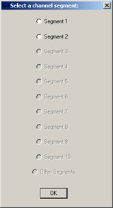
Select a channel segment from the list provided in the dialog box shown in the sidebar. If there is only one channel segment, the interpolation will be completed directly. Note that before interpolation, the channel slope profile may look like a stair case because only the surveyed cross-sections define the channel profile at this point. Following interpolation, the slope profile will be more representative of the actual river profile.
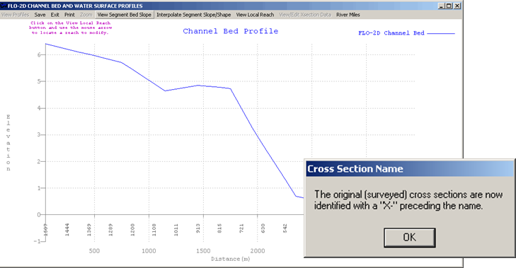
PROFILES will automatically locate the surveyed cross-section data and interpolate the cross-section geometry and elevation (thalweg slope) for all those channel elements between the surveyed cross-sections within the segment. The following dialog box will appear indicating that the original cross-sections have been renamed with a prefix ‘X-’ before each cross-section name.
Click ‘OK’ in the dialog box to view the interpolated bedslope.
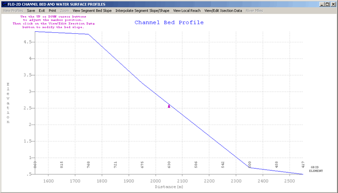
Click on the ‘View Local Reach’ button on the menu bar. Click anywhere along the bedslope profile to zoom in on a local reach of 10 channel elements.
Click on ‘View/Edit Cross-Section Data’ to view the following dialog box displaying the channel element characteristics:
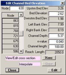
Click on the ‘Xsec’ button in the dialog box to view the cross-section data and image.
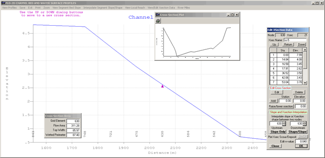
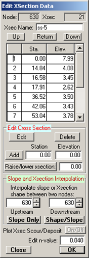
View additional cross-sections by clicking on the “Up” and “Down” but- tons in the dialog box. The computed cross-section geometry and all the cross-section station and elevation data can be reviewed and edited. Edit the channel and cross-section data by adding or deleting stations and elevations, revising the Manning’s n-value, or raising or lowering the entire cross-section.
Interpolate bedslope and or channel geometry. Identify the Upstream and Downstream channel elements in the group boxes labeled ‘Slope and Xsection Interpolation’. Use ‘Up’ and ‘Down’ buttons to locate one of the surveyed cross-sections and then type in the other either upstream or downstream channel elements. There may be several channel elements between two cross-sections selected for interpolation. Click on either the ‘Slope Only’ or ‘Shape/Slope’ buttons to interpolate either the channel bed slope or slope and the cross-section shape. The cross-section geometry is linearly interpolated according to top width and distance and is adjusted for the weighted flow area. One cross-section is overlaid on the other cross-section, stretched or contracted and the elevations averaged.
Save the results frequently by clicking on ‘Save’ on the menu bar. The saved data will not be written to file until the program is closed.
Note
Perform the initial channel interpolation of the cross-sections automatically with the FLO-2D plugin.